3D Scanning and Pavement Surveying
Over 9 million Points Per Mile at Highway Speeds. Immediately Report IRI.
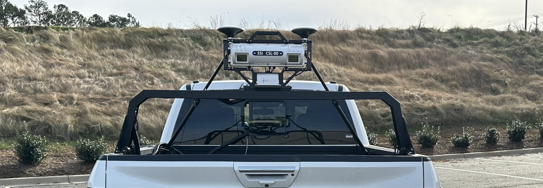
Collect Data at Highway Speeds With a Fixed Sampling Interval
Elevation Accuracy
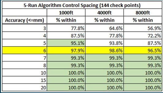
SSI supplies users with SSI software to merge and correct multiple overlapping scans. Merging creates complete surface coverage and limits sensor drift. If a true 3D point cloud is desired, a survey crew captures points within the grid of the scan. SSI software corrects the vehicle scans to each other and to the surveyor’s elevation to achieve 6mm vertical accuracy for over 95% of the point cloud.
Operators don’t need to worry about radio signals and RTK. All GPS corrections are performed with Post-Processed Kinematic (PPK). SSI’s correction software can also add PPP GPS corrections or multiple PPK base stations.
- Fixed sampling interval set by operator before collection
- Maximum vehicle speed set by sampling interval
- Correction points are collected on the scanned surface by surveyor
- Vehicle scans only need to overlap a few inches
- 4,000 foot correction point spacing yields 95% of points within 6mm
- Inertial Profiler system is integrated within scanner
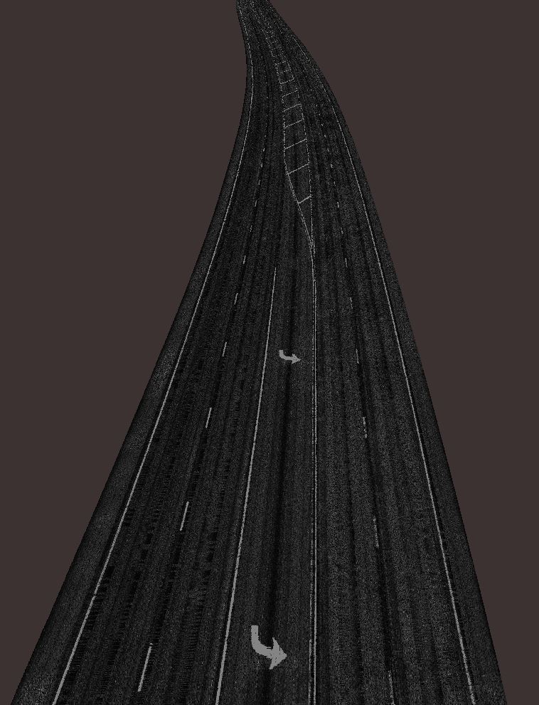
View Lane Lines with Laser Intensities
The lasers sensors also output the intensity value – or the contrast of black vs white. These intensity values can be used to detect lane lines or colored marks on the pavement or track surface.
Smoothness Based Design Models
Users may use the scan data and extract lines to create variable depth milling or paving models.
Through the SSI Profile Design module within the SSI Profiler software operators can fix cross-slope and set tolerances for cut depth or paving depth. This will output a GPS and station indexed model to be used for machine control or project estimates.
SSI is continually developing tools to identify and improve high roughness projects. Most projects don’t require machine control, but if you have questions contact SSI to help meet your project’s smoothness goals.
Accurate Cross Slopes
SSI systems can incorporate a military grade INS-GNSS system to measure vehicle dynamics. The INS system also improves GPS position output with more satellite constellations and position memory. Better position gives operators more accuracy for distance measurement with a GPS-DMI and location navigation.
This INS unit can be paired with SSI inertial systems to output accurate cross-slopes throughout the collection. The SSI software uses a simple calibration to offset mounting and sensor variables to report accurate measurements. These measurement have correlated within 0.1% of digital level verifications.
The cross-slope can be reported for every sample or averaged over an user-inputted interval.
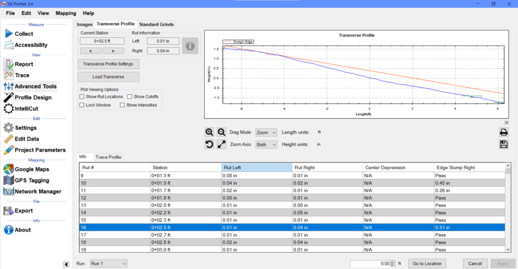
Collect Edge Slump Measurements
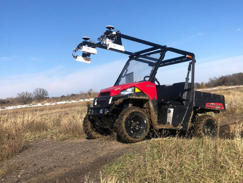
Through transverse profile collection systems like the CS9500 Full Lane Survey Profiler and the CS8750 Lightweight Survey Profiler the edge slump of concrete pavement can be reported. SSI developed report to match the field measurements of the 12-foot straightedge per the FAA specifications. Data can be collected at a continuous speed between 0-50mph with a Polaris side-by-side on the CS8750. The CS9500 vehicle mounted system can also be used if the concrete allows vehicle traffic.
Designed For Accuracy, Built For Efficiency
Different Vehicle Platforms - Same Technology
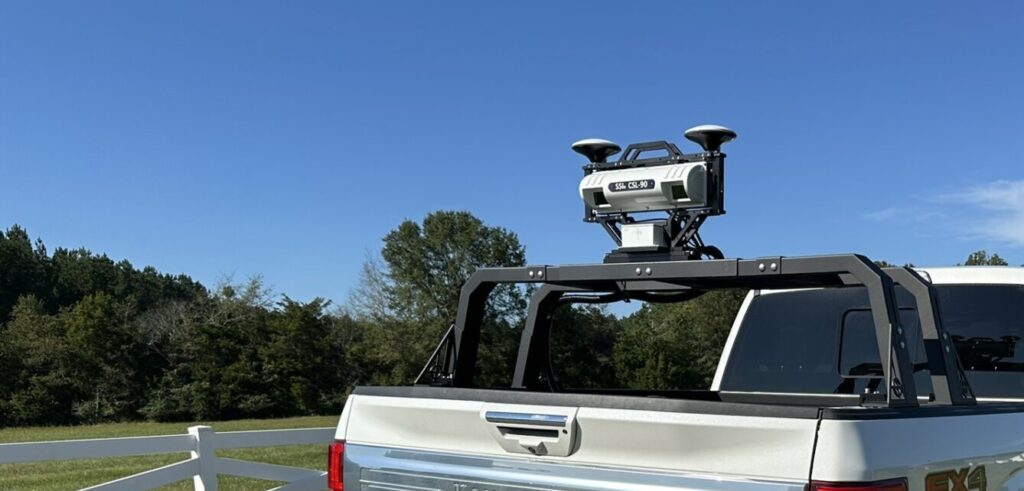
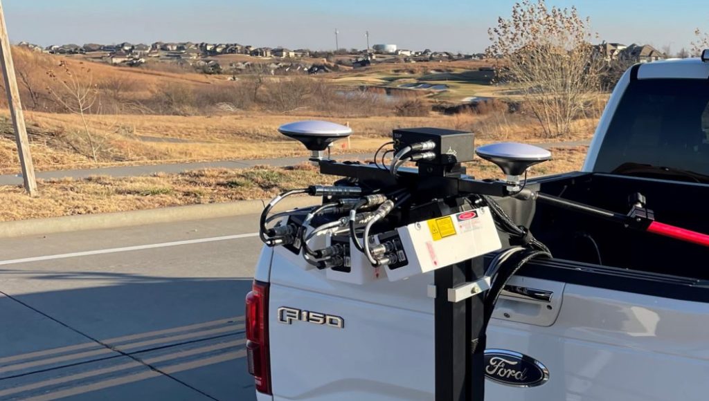
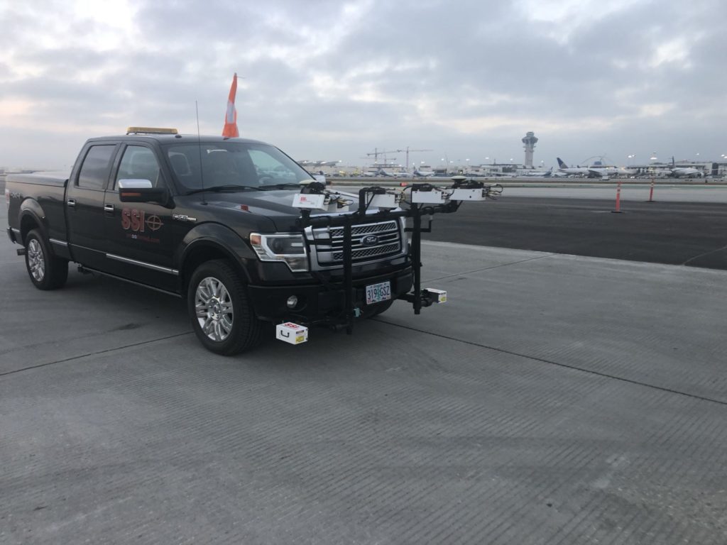
SSI’s CS9500, CS9550, and offroad profilers use the same technology with a different scale. The typical CS9500 system has six transverse lasers, CS9550 has three lasers, and the typical offroad Polaris survey system has four lasers. Each system uses the same software and the modules are interchangeable.
Data Quality Specifications
CS9500 or CS9550 acts as an inertial profiler capable of certifying under ASTM E950, AASHTO r56, or TxDOT 1001-S standards. No other system can reliably and easily convert and mimic an inertial profiler. IRI data is collected simultaneously with the survey point cloud.
We use more sensors for higher accuracy. The SSI scanners maintain higher point-to-point and survey elevation accuracy than comparable LiDAR or scanning systems.
- Data Sampling
Wheelpath data sampled at 1-inch at highway speeds (user can adjust sampling for specialized collections)
Data for point cloud is sampled at user specified fixed interval. Data can be resampled after collection in post-processing - Optical encoder Distance Measurement Instrument (DMI)
Accuracy of 0.1% - Vertical Acceleration
Host vehicle suspension dynamic measured with aerospace grade accelerometer sensors (rated for up to +/- 5g or 10g; resolution to 0.0001g). - Profile Feature and Wavelength Preservation
Proven ability to measure and preserve fine surface features more accurately than any competing system. Standard profile wavelength preservation from ~0.25 feet (76.2 mm) in excess of ~8,000 feet (2,438 meters). With optional survey subsystem added to SSI profiling system, long wavelengths preservation is thousands of feet (theoretically infinite). - Repeatability & Accuracy
Guaranteed to meet or exceed industry standards and specifications (including ASTM E950, AASHTO M328, R056, and DOT including Texas 1001-S).
Configure Data Outputs and Sampling
- Collection speed 0-100mph with Zero-Speed, 5-74mph without (0-161 kph or 0-119 kph)
- CS9500 scan width 12 to 14 feet (3.6 to 4.3 meters)
- CS9550 scan width 7.5 to 8 feet (2.3 to 2.4 meters)
- Fixed Sampling interval set by user – not collection speed
- Data can be resampled during processing
- User selects scanning sampling rate while wheelpaths always collect 1-inch samples for IRI and profile data.
- Export to LAS, PNEZD, CRG, CSV
- Export to Lat/Long, UTM or State Plane
- Resample data if needed from original sampling interval
- Extract station intervals or specific lines from point cloud
- Extract the surface at the collected sampling interval or resample it down to a manageable size.
Hardware
Scanning Lasers
- 5KHz wide beam Class IIIB lasers
- 1200 points per profile across 2.3 ft/70cm
- Resolution (X): 0.27 mm – 0.80 mm
- Linearity (Z): 0.05% of MR
- Resolution (Z): 0.154 mm – 0.56 mm
IRI or Texture Lasers
Visible light laser, scanning at 5 KHz. Wide or standard laser beam width available.
- 4 or 6-inch wide beam (100 or 150mm)
- Laser vertical measurement resolution is between 0.015 and 0.56-mm, depending on laser type.
- The lasers have a 3B/lllb classification under the standards relating to laser products specified in IEC 60825-1 and U.S. FDA CFR Title 21 Part 1040 and Laser Notice No. 50, dated July 26, 2001
Accelerometers
Aerospace grade single axis accelerometer sensors for measuring vehicular vertical acceleration.
- Measurement range: +/- 10g
- Resolution: 0.0001g.
Optical Encoder
Wheel mounted high resolution optical encoder for fine increment distance measurement.
- Longitudinal distance accurate to 0.1%.
- Optional GPS based distance measurement
GPS Receiver
Multiple GPS receivers are available from SSI. For survey systems, the GPS is embedded with the INS system for added satellite constellations, reception reliability and accuracy.
- Embedded GPS, Glonass, Beidou, Galileo constellations optional
- Over 35 satellites available
- Up to 100Hz Sampling
- PPK Horizontal Accuracy: 1 cm
- PPK Vertical Accuracy: 2.5cm
- PPK scanning elevation accuracy with correction points: 6mm for 95% of points
- IMU Pitch and Roll Accuracy: 0.02 degrees
- IMU Heading Accuracy: 0.1 degree
- IMU Velocity Accuracy: 0.02 m/sec HRMS
- Satellite Signals: L1/L2
- Cold Start, Time to First Fix: <60 seconds
- Dynamic Range (Gyro, Accelerometer): 125˚/s, 8g
- Bias Instability (Gyro, Accelerometer): 0.8˚/h, 3.2µg
Operation and Installation of System
- Operator Interface Computer
Mil-Spec tested Panasonic Toughbook 20/31 ruggedized notebook computer (typical CF-31 configuration: Intel i5/i7 processor, Microsoft Windows 10 operating system, minimum 2GB RAM (expandable to 4-8 GB); minimum 160-320GB hard drive, optional DVD multi-drive, Gigabit Ethernet LAN, wireless 802.11 a/b/g/n, 13.3” SVGA display with outdoor readable touch screen; under 8 lbs; lithium-ion internal battery. Additional options and accessories available for Toughbook computer. - Profiling System Sensors
Industrial / aerospace grade sensors. System supplied with durable shielded cables with Amphenol connectors. - Mount Hardware
Professionally engineered mount hardware for attachment of inertial profiling system components onto front or rear of industry standard vehicles. Portable systems attach to standard 2 inch (5.08cm) square receiver tube and operate from host vehicle’s 12V power supply. - Flexible DMI Hardware
Hardware supplied for attachment of high resolution distance measurement interface to rear wheel of host vehicle. Dedicated lug-extenders or optional collets supplied. - Sensor Adjustment
Dove-tail hardware supplied for horizontal and vertical adjustment of laser / accelerometer sensor modules. - Adaptor Hardware
Custom hardware design and fabrication available for profiling system attachment according to customer defined requirements or specifications (front, rear, or mid-vehicle mount).
Software
SSI Profiler 3 Software Suite
SSI internally developed software routines for profiling system calibration, data collection, data analysis and reporting. On-screen instructions for system calibration and data collection. Feature rich data analysis software. Current versions built on over 20 years of continuous development.
- Profiling Programs Fully Compatible With Microsoft Windows
All software fully integrated with Microsoft Windows 10 (also Win7) - Multiple Calibration / Diagnostic Routines
Menu driven calibration routines for distance, proprietary accelerometer static calibration (in-field), bounce test (data file saved), laser height verification (0.25”/0.5”/1.00”/2.00”), rut-depth (if equipped) and cross-slope (if equipped). Internal diagnostics provide real-time monitoring of profiling system health. - User-Selectable Parameters
English or Metric units for both data acquisition and reporting; new file parameters become default (no recurring new file setup). Industry standard and user definable parameters to facilitate identification, authentication and sharing of profile data. - Real Time Display
Real time display of vehicle position and surface profile trace during data collection. - Multiple Data Collection Triggers
3 data collection triggers: (i) SSI Reverse Direction Trigger (proprietary procedure that collects exact stations without pre-marking test sections and post-testing cone removal), (ii) Electric Eye, and (iii) On-the-Fly. - Event Marking
Entry of location notes by (i) push button or electric eye, with text editing by operator after safe finish of data collection, or (ii) user configurable hot keys (assigning unique event types to particular keyboard buttons). - Urban Area Data Collection
Zero-speed option allows collections of accurate, repeatable data throughout vehicle stoppages. Collect data at any speed from 0-100 MPH. No need for lead-in or run out sections with the zero-speed option. Systems without zero-speed option have SSI “Continuous Collection” software standard, which automatically suspends the collection when speed drops below 5 MPH and resumes collection when the vehicle resumes forward travel over 5 MPH. - Pause Function with Data Retained
Pause data collection manually or with electric eye. Data from paused sections retained for reporting separately or combined with non-paused areas. - Multiple Profile Indexes
Profile data reported in multiple indexes Profile Ride Index (PRI), International Roughness Index (IRI)(by segment or continuous), Mean IRI (MRI), Half Car Ride Index (HRI), Ride Quality Index (RQI), and Ride Number (RN). - Localized Roughness
Multiple outputs of localized roughness supported. Rolling straightedge, profilograph must grind bump/dip template, Texas 1001-S localized roughness, IRI areas of localized roughness reported according to user specified IRI thresholds. Dimensions of localized roughness calculated by length of defect and peak amplitude. - Re-Writeable Data with Variable Data Analysis Parameters
Raw profile data infinitely rewritable for outputting reports and profile traces under user adjustable parameters. - Variable Filtering
Raw inertial profile data can be filtered with low pass filters (0.5 ft to 1.0 ft.) and standard high pass filters 100/200/300 ft, with scalable custom filter lengths of up to 800 feet or more for custom applications. - Multiple Trace Reporting
Patented multiple profile trace data acquisition and reporting capability. Single sensor systems report dual tracks (separately collected in either direction). - Data Conversion Sub-Routines Supplied
Export routines for conversion of profile data to industry specified formats (ERD, PPF, PRO, ASCII, CSV, Excel, Text, raw profile/ProScan, GIS and customized per request). - One Touch PDF Images
Create universally readable PDF images of profile traces and reports directly within SSI Profiler program. - Multiple Software Licenses
Data analysis software licenses provided for profiling system and desktop computer usage. - Data Encryption
Encrypted raw data files for data integrity security, raw data by repeat analysis under adjusted parameters.
SSI Survey Correction Program
Add in scan data from the CS9500 system and correction points from the surveyor. These correction points can be used to adjust the scan elevations to be within 6mm for over 95% of the points. The merged scans and corrected data can be exported as an LAS. Use these LAS point clouds to extract lines to create 2D or 3D reference models or compare surfaces for material quantity analysis.
Operational and Dimensions
- Dimensions & Weight:
- Laser/Accelerometer Modules: 8” L x 4” W x 4”H • 5 lbs
- Core Electronics Module:
- 8” L x 5” W x 5”H. 6 lbs
- Housed in secondary enclosure: 12” L x 16” W x 6”H • 6 lbs
- Mount Hardware:
- CS9500: 72” L x 12” W x 40”H (152 cm L x 20.3 cm W x 61 cm H) • ~80 lbs (34 kg)
- CS9350: 60” L x 10” W x 24”H (152 cm L x 20.3 cm W x 61 cm H) • ~50 lbs (34 kg)
- CS8750: See Polaris Ranger 500EFI
- Environmental:
- Temperature: Operating ambient temperature range: 32° to 128° F (0 to 53° C); non-laser component operating temperature range: 0° to 140° F (18-60°C). Storage temperature range: -25° to 160° F (-32-71°C).
- Humidity: Operating humidity should not exceed 90 percent (noncondensing); non-operating humidity range shall not exceed 100 percent (noncondensing).
- Moisture: Profiling system components impervious to moisture. Quality of surface measurements degrade with excessive moisture. Recommend against use with active rainfall, standing water or ponding on surface.
- Power Attributes:
- Consumption: 120 W max
- Input voltage: +8 to +16 VDC
Optional Features
- Zero-Speed Inertial Profiler Upgrade
- INS-DMI
- Single or Dual Texture Measurement
- One to six lasers for rutting and point cloud measurement
- Intellicut Corrective Grinding Simulator
- Profile Design Variable Depth Modeling Software
- Network Manager to collect continuously off of GPS data
- “Starter” hardware to begin with a dual laser inertial profiler or CS9550 and build up to a full transverse system
Standard Features for SSI Survey Scanners
- High Accuracy GPS Receiver
- Ability to log INS data for PPK
- PPK software built into collection program
- SSI Profiler program to collect, view, report, edit, post-process, and export
- Embedded PPK correction routine
- SSI Survey Correction program for merging and correcting point clouds
- Google Maps and Google Earth Compatability
- Export formats to: Shapefiles, PDF, CSV, txt, PRO, ERD, PPF, LAS, PNEZD
- Some form of IRI collection and reporting of profiles
- Straightedge, IRI, MRI and profilograph localized roughness analysis

